Import of Resources
- Manage Imports
- Import Dialog Options
- How to Import Resources
- Import Raw Resources
- Import Benchmarks
- Import from Solution
- Smart Importer
- Smart Importer UI
- Basic Operations
- Smart Importer UseCase
- Recommended Layers Structure for Smart Importer
- Adobe XD Importing
- Figma
- The example file of Figma
- Automatic Imports
- Image Update
- glTF Files
- Skinning
Manage Imports
Manage Imports
The Scene Composer Solution Explorer enables users to manage and organize all files associated with a solution. Imported resources can be arranged into folders based on user requirements, and this folder structure is linked to the directory structure stored locally on the system.
For additional details on managing solutions using folders, refer to here.
The folder organization of imported resources can be modified directly within the Solution Explorer panel. In addition, some imported assets may also appear in the Imports panel.
Original Image File Retention
When an image file is imported via the menu File > Import > Import Resources, Scene Composer retains both the original image file and the associated bitmap information file (*.bin), which is used internally by the application.
Original image files are not retained when importing formats such as FBX or glTF, nor when resources are imported using the Smart Importer.
Original Image File Name
The name of an imported image is constructed as follows:
- the image information name + the original image file extension
The name of the original image file is displayed in the Original Image section of the Properties panel for the imported resource.
If the resource file name is modified in the Solution Explorer, the corresponding original image file name is automatically updated as well.

Original Image File Location
The Solution Explorer displays only the bitmap information file (*.bin), the original image file is retained in the local Solution folder. This folder mirrors the directory structure shown in the Solution Explorer.
Here is how to easily view the local file system location of a resource:
- In Solution Explorer, select the resource.
- Right-click the selected resource.
- The context menu is opened as shown in the figure below.

- The context menu is opened as shown in the figure below.
- In the context menu, select Open In File System.
- Windows Explorer is opened, displaying the folder that contains both the bitmap information files and their corresponding original image files (see figure below).

Moving Original Image Files
When an imported resource is moved from one folder to the other within the Solution Explorer, its original image file is moved together with the corresponding locally stored bitmap information file.
Imports Panel
The Imports panel can be displayed or hidden via the menu option View > Libraries > Imports. This panel presents imported resources in a hierarchical structure. Resources listed in this panel can be added to the scene - either in the Scene Editor or the Scene Tree Panel - by using drag-and-drop operations.

Properties of Imported Resources
When an imported resource is selected in either the Solution Explorer or the Imports panel, its properties are shown in the Properties panel. By default, this panel is located in the lower-right area of the interface and provides detailed Information about the currently selected resource.

Clone, Delete and Rename Items
Imported resources can be cloned, renamed or deleted within the Solution Explorer panel. To perform these actions, right-click the desired item in the Solution Explorer and select the appropriate option from the context menu.
Additionally, you can right-click a folder containing imported files to delete multiple resources at once.
For more information, see the Context Menu section of the Solution Explorer documentation.
Delete Unused Imports
If a solution contains unused imports or import components, they can be removed to clean up the project by using the Delete Unused Imports... command. This command is available from the following locations:

The Delete Unused Imports dialog displays all imports included in the solution, allowing you to review and remove those that are no longer referenced or required.
Imports currently in use - and therefore not eligible for deletion- are displayed in a disabled (greyed out) state. You can toggle the visibility of these non-deletable items using the Filter button located in the upper-right corner of the dialog.

To delete unused imports, select the checkboxes next to the items you want to remove and click Delete.
Import items that can be identified and removed as unused include:
- Images
- Raw resources
- Fonts
- Fragment shaders
- Vertex shaders
- 3D model files
- Scripts
If an import folder contains additional files or folders that are not part of the imported resources, the folder itself is not deleted. Only the unused imported files within that folder are removed.
Export Imported Images
Imported images can be exported from the solution as .png files. This option is available in the context menu when right-clicking an imported image. The export operation also supports multiple selection, allowing multiple image resources to be exported at once.
An imported image can be exported even if it is in a locked state.
- Solution Explorer
- Imports panel
- Canvas Node
- Canvas sprite
- Billboard
To export an imported image as a .png file:
- Select the imported image you want to export.
- Right-click on the selected image.
- The context menu is opened (see figure below).

- The context menu is opened (see figure below).
- In the context menu, select Export Image To...
- The Windows Save As dialog appears.
- Choose a destination folder and specify a file name, then click Save.
- The image is exported and saved in .png format.
-
Currently, the export operation outputs the original image file rather than the processed asset version.
Edit an Imported Script Resource
Scripts can be imported via the menu using Import > Import Resources... By default, imported script files are read-only; however, they can be converted to an editable format if modifications are required.
To make an imported scripts editable:
- In the Solution Explorer, select the script resource.
- Right-click the script and choose Change to Editable from the context menu.

For instructions on working with script resources, refer to the Scripting documentation.
Import Dialog Options
This section describes the configuration of the Import dialog that appears when importing resources such as FBX files, images, shaders, fonts, or scripts.
The available options within the dialog may vary depending on the type of asset being imported.
Import Dialog

| 1 |
Comparison: Resources at the import destination are compared with those included in the current import, and the resulting update status is displayed. The import status is indicated by icons and tooltips in the Status column and is also reflected by the font color of each resource name in the After Import column. Green: A new resource will be added. |
| 2 |
Save Report…: Generates and saves a report file (CVS format) summarizing the comparison results for the imported files. The report name and save location can be specified in the dialog that appears when this button is clicked. |
| 3 |
Select Files…: Opens a dialog that allows you to choose the items to be imported into the solution. |
| 4 |
Folder: Select the destination folder for imported files. Use the drop-down menu or the Browse button to select any location in the Solution Explorer as root folder for the import destination. By default, the root folder /Resources is selected. |
| 5 |
Create new folder for import: Enable this option to create a new subfolder within the selected destination specified in (4) Folder. Enter the name of the new subfolder in the provided input field. |
| 6 |
Delete existing items in destination folder: When enabled, all existing content in the destination folder is deleted before the import operation is performed. |
| 7 |
Preserve imported folder structure: This option is available only when importing Image or 3D model file types, and it can be enabled only if Delete existing items in destination folder is active. When selected, all existing files in the destination folder are removed while retaining the existing folder structure. *Note: This option is not available when importing Font or Shader file types. |
| 8 |
Visible in imports panel: When enabled, imported items are displayed in both the Imports panel and the Solution Explorer. |
| 9 |
Preserve library item attributes: This option allows you to retain specific item attributes during a re-import operation. When enabled, previously assigned attributes remain unchanged, even if newly imported data contains different values.
Attributes that can be preserved include: - Bitmap properties: Converter, Target format, Origin - Vertex buffer properties: Buffer type, enable cache, position, normal, texture coordinate, tangent, bi normal etc.
When preservation is applied, the re-import process does not overwrite these properties, regardless of the differences in the incoming data. |
| 10 |
Set bitmap profile: Specifies a default bitmap profile applied to all bitmaps that do not have an explicitly assigned profile. This option is available when importing Images, FBX, and glTF files.
Bitmap profiles can be configured in the following ways: - From the menu bar: Solution > Solution Options... - From the Properties panel, which appears when selecting the target resource in the Solution Explorer. |
| 11 |
Import as wireframe: This option is available only when importing FBX files. When enabled, a wireframe vertex buffer is generated based on the triangles and rectangles defined in the FBX file. Both the standard vertex buffer and the wireframe vertex buffer are then registered under Associated Vertex Buffer in the Solution Options. |
| 12 |
Set the "Is Indexed" property of the vertex buffer to enabled: This option is available only when importing FBX files and is enabled by default. |
| 13 |
OK button: Imports the selected resources using the configured settings. |
| 14 |
Cancel button: Closes the dialog without performing the import operation. |
| 15 |
Radiance HDR Format: Available formats include:
|
In an OpenGL ES 2.0 environment, none of the available Radiance HDR Format options (RgbFloatingPoint9E5PixelFormat / RgbFloatPixelFormat / RgbHalfFloatPixelFormat / RgbaFloatPixelFormat / RgbaHalfFloatPixelFormat) are supported. If any of these formats are present in the solution, a warning is displayed in the Problems panel.
SVG Importer Dialog

| (1) |
Import Settings Import to folder: Specifies the destination folder in the Solution Explorer where the SVG file will be imported. Create new folder for import Enables the creation of a new subfolder within the selected destination. Enter the name of the new subfolder in the input field provided. Importing List Displays the items selected for import. - Items that cannot be imported are indicated with an error icon. - Items that can only be partially imported are indicated with a warning icon Even if no icon is displayed, certain elements may still fail to load due to their content or structure. |
| (2) |
Add/Delete: Add: Adds an additional SVG file to the list of items to be imported. |
| (3) |
Preview Display: Left-side: Displays the original SVG image selected from the Importing List In the current version of Scene Composer, the previewed size may not always match the original dimensions of the original SVG image. |
| (4) |
Error Message: Displays any warnings or errors associated with the selected file. |
| (5) |
Import/Cancel: Import: Imports all items listed in the Importing List. |
How to Import Resources
This section describes how to import resources by selecting Import Resources... from the Import menu on the menu bar.

Import File Formats
You can import the following file formats using this menu:
- Image files (
*.bmp, *.jpg, *.jpeg, *.gif, *.tga, *.png, *.dds, *.ktx, *.hdr, *.exr) - Font files (
*.ttf, *.ttc,*.otf, *.fnt, *.fbm, *.*) - Shader files (
*.vert, *.frag) - SVG files (
*.svg) - FBX files (
*.fbx) - glTF files (
*.gltf, *.glb) - Icon files (
*.bmp, *.ico, *.jpg, *.png) - Script files (
*.lua)
Beside the formats listed above, Scene Composer also supports importing Photoshop (*.psd) and Adobe XD (*.xd) files. For more details on importing these formats, see the Smart Importer chapter.
When importing font files, the application recognizes and imports them as fonts, regardless of their file extensions. For more information, see the explanation here.
Beginning with CGI 3.14, Scene Composer can play back skinning animations after you import skinning-enabled FBX or glTF files.
About .glTF File Format
SceneComposer supports the following glTF file formats during import:
- glTF: References external binary data (geometry, animation keyframes, skinning data), and image files.
- glTF-Embedded: Contains base64-encoded binary data, and images embedded inline using data URIs.
- glTF-Binary: Packages the entire glTF asset (JSON description, .bin binary data, and images) into a single binary file.
For more detailed information on these file formats, see the Khronos website: GLB File Format Specification.
About .ktx File Format
Scene Composer supports the following compressed image formats:
- Etc2CompressedRgbFormat
- Etc2CompressedSrgbFormat
- Etc2Alpha1CompressedRgbaFormat
- Etc2Alpha1CompressedSrgbaFormat
- Etc2EacCompressedRgbaFormat
- Etc2EacCompressedSrgbaFormat
To use these formats, you have to convert the source image from a supported image type (such as .tga, .gif, .psd, .bmp, .pgm, .png etc.) into a .ktx file. You can use the following tools to create KTX files:
- Texgenpack
- Mali Texture Compression Tool
- Ericsson Texture Compression Tool
These tools compress texture images using Ericsson Texture Compression (ETC/ETC2) and Adaptive Scalable Texture Compression (ASTC). They supports the following output formats:
- .pkm - Contains compressed textures
- .ktx – Stores a 2D texture along with all associated mipmap levels.
After conversion, you can import the .ktx file into Scene Composer following the same process as for other image formats.
-
When importing a converted .ktx file into Scene Composer, you cannot use the DefaultBitmapConverter property that is available for standard .bmp images.
About Bitmap Font
Scene Composer supports the use of bitmap fonts. To enable the bitmap font functionality, you must compile the SCHost.dll using the BitmapFont engine. Note that only one font engine can be active at a time within an instance of SCHost.dll.
The following file types can be imported as bitmap fonts:
- .fnt - Scene Composer converts these Windows font files to bitmap fonts.
- .fbm - Pre-converted bitmap font files
When you import a font, Scene Composer sets the following property:
- Source file names - Indicates the name of the imported file, helping you identify a font

On OpenGL ES1.1 platforms, such as Traveo2, importing shader files, SVG files, FBX files, and glTF files is not supported.
Import Operation
Open the Import Dialog in one of the following three ways.
Menu Bar
Select Import > Import Resources... from the menu bar.

Context menu
Right-click on any folder in Solution Explorer and select Import > Resources... from the context menu.

Drag and Drop
Drag and drop the target file that you want to import into any folder under Solution in Solution Explorer.

-
- You can also import a glTF file by drag and drop to any folder under Solution in Solution Explorer.
- Note that in an OpenGLES1.1 environment, you cannot import shader files (*.vert, *.frag), SVG files (*.svg), FBX files, and glTF files via drag and drop.
- When you drag an image file format (*.bmp, *.jpg, *.png) that Scene Composer can import as an icon into any folder under Solution in Solution Explorer, a dialog box appears, allowing you to choose whether to import it as an image or icon resource.

- You can also import a glTF file by drag and drop to any folder under Solution in Solution Explorer.
Save Solution
When you start the import process, Scene Composer checks your solution for unsaved changes. If necessary, you are prompted to save your solution. Click OK to proceed. Once the solution is saved, Scene Composer opens the Import Resources dialog.

To hide this dialog from popping up at future imports, clear the Always show this dialog checkbox.
Import operations by file format
After you select a file, Scene Composer shows different import operations depending on the file format. See the following topics for detailed import procedures.
Image, font, shader, FBX, and script files
For importing FBX files that contain skinning, see here.
When you import an image file, Scene Composer retains the original image file along with the bitmap information file (*.bin file) used on Scene Composer. See here for details.
-
In the Import Resources dialog, select one or more resource files that you want to import and click OK.
- Search for supported file formats by selecting them in the drop-down menu at the bottom right of the Import Resources dialog.
- Import multiple files at once as long as their file format belong to the same category, such as Image files or a Font files.
- Select Font files from the pull-down menu below, to import any file as a font file, regardless of its extension.

-
After you selected the files to import, Scene Composer displays an Import dialog for the selected file type (Image, Font, FBX, Shader…).
-
See Import Dialog Options for a description of the settings on the dialog screen.
- Select Import as wireframe check box to import the wireframe vertex buffer when importing an FBX file.
- When the import selection contains Radiance HDR (.hdr) files, a Radiance HDR Format option appears in the Import dialog.
-
The available choices and the default value follow the setting made in the Import Images Config panel of Solution Options. See Import Dialog Options for details.

-
-
Configure the import settings, then click OK.
-
Scene Composer imports the file as a resource in Solution Explorer.

-
Wireframe Related Properties
When importing an FBX file with the Import as Wireframe option enabled, a Line Width property is added to the Mesh property item of the target node. This property specifies the line width of the mesh when Scene Composer renders it as a wireframe.
- Scene Composer determines the actual line width by rounding the specified width to the nearest integer.
- If the setting is less than “1”, Scene Composer always sets it to “1”.

FBX files with multiple animations
Scene Composer supports the import of FBX files that contain multiple animation tracks. Scene Composer automatically creates the names of the imported animation tracks based on the animation tracks contained in the FBX file.

You can import the following types of animations from FBX files:
- Translation
- Rotation
- Scaling
Icon files
See Icon Picker for information on how to use imported icon resources.
-
In the Import Resources dialog, select the target file, then click OK.
-
If the selected file format is "*.ico", Scene Composer displays the Import Icons dialog that provides the following options:
- The Selected files field displays the path to the selected file. To re-select a file, click Select File... .
- In Destination folder, specify the location where Scene Composer imports the file as a resource.
- As explained in the Drag and Drop section, when you drag and drop an image file (*.bmp, *jpg, *.png) that can be imported as an icon, Scene Composer displays a prompt allowing you to select whether to import it as image or icon.

- The Selected files field displays the path to the selected file. To re-select a file, click Select File... .
-
Click OK to complete the import operation.
SVG files
-
In the Import Resources dialog, select one or more SVG files that you want to import and click OK.

-
Scene Composer displays the SVG Importer dialog:
-
See SVG Importer Dialog for a description of the settings on the dialog screen.

-
-
Configure the import settings, then click Import..
-
Scene Composer creates the ImportedScenes and Scenes folders at the destination folder selected in Solution Explorer. The former holds data imported as template scenes, while the latter holds data imported as actual scenes.
-
If you import multiple SVG files, the Scene Editor displays the actual scene that corresponds to the topmost SVG file in the SVG Importer.
-
Transform > Position > X = 0, Y = 0 is the item's initial position.
-
-
You can copy group nodes from imported scenes and paste them into your desired scene to use them.

-
glTF files
The CGI Studio glTF Importer does not support the following features:
- Morphing
- Vertex Buffer Streams
- Sparse Accessors
For additional details on handling glTF files — e.g., supported extensions, multiple UV sets, and limitations — see the glTF file page.
For importing glTF files that contain skinning, see here.
-
In the Import Resources dialog, select one or more resource files that you want to import, then click OK.
-
Scene Composer displays the Import GLTF dialog:
-
When you check Import Dynamic Appearance, Scene Composer imports the file with a dynamic GltfAppearance. When you clear it, Scene Composer imports the file with a static Appearance.
-
When you import the file with a dynamic GltfAppearance, Scene Composer attaches a GltfAppearance to Mesh, SkinningMesh, and SkyBox, and you can edit the glTF 2.0 material properties directly in the Properties panel. For details about each property, see Properties Overview.
-
When you import the file with a static Appearance, Scene Composer configures the appearance as a combination of shader uniforms and textures. For details, see Physically Based Shading (PBS) on the glTF file page.
-
When you import a glTF file that uses KHR_materials_transmission, Scene Composer automatically creates the render targets and cameras that transmission requires. For details, see Importing Transmissive Materials on the glTF file page.
- Use the import dialog to configure Image-Based Lighting (IBL). You cannot change these settings after the import.
- If you do not want to use IBL, clear the Use Image Based Lighting (IBL) checkbox.
- During glTF import, the Engine automatically generates the IBL from a single HDR panorama (latlong) image, so you do not have to set the radiance, irradiance, or BRDF integration textures manually.
- Configure HDR Panorama (Latitude/Longitude) Image, IBL Cubemap Texture Size, and IBL Lookup Texture Size in the import dialog as necessary.
- IBL cubemap textures size: Specifies the size of the cubemap texture used for IBL generation. The default value is 256. On ES2.0 platforms, the minimum value is 64 and the size must be a power of two. On ES3.0 platforms, the minimum value is 64.
- IBL lookup textures size: Specifies the size of the lookup texture used for IBL generation. The default value is 256. On ES2.0 platforms, the minimum value is 64 and the size must be a power of two. On ES3.0 platforms, the minimum value is 64.
- You can also set IBL in Solution Options. For details about these settings, see IBL HDR.

-
- After confirming by clicking OK, Scene Composer displays the Import GLTF dialog:
- You can’t change IBL settings in the import dialog (red box below).
- When you specify an HDR panorama image and run the import, the Engine automatically assigns the generated shared IBL textures to each mesh (orange box below).
- The Engine generates the following textures: LambertianTexture (Diffuse/Irradiance), GGXTexture (Specular/Radiance), GGXLutTexture (BRDF 2D LUT), and SkyBoxTexture (Skybox).
- For other settings on the dialog, see Import Dialog Options.

- You can’t change IBL settings in the import dialog (red box below).
-
Configure the import settings, then click OK.
-
Scene Composer imports the file as a resource in Solution Explorer , based on the selected dialog settings.

-
Shared IBL textures
When you import a glTF and generate IBL from an HDR panorama (lat/long), the importer automatically assigns the shared IBL textures (LambertianTexture/GGXTexture/GGXLutTexture/SkyBoxTexture) to each mesh. When you change a shared IBL texture, the importer propagates the change to all meshes that reference the shared IBL texture.
In the example below, select LambertianTexture (Diffuse/Irradiance) in Solution Explorer and set Magnification Filter to Nearest in the Properties panel. The importer applies the same setting to every mesh/material that references LambertianTexture.

Import Raw Resources
To import any type of raw resource, select Import > Import Raw Resources... from the menu bar.

-
You can import raw resources in SceneComposer by dragging them onto the Solution Explorer panel.
In the Import Raw Resources dialog, click the Select Files... button. SceneComposer opens the Open File dialog. In this dialog, select one or more raw resources to import, then click OK.

Click Save Report... to save the content of the Comparison tab in CSV (Comma Separated Values) format. In the Save As dialog, enter a name and select the location for the CSV file.
For a description of the Import Raw Resources dialog's checkboxes, refer to Import Dialog Options.
To compare new content with already imported resources, right-click a raw resource, to open the Compare Properties dialog.
Problems: Import Conflicts
SceneComposer's Problems panel lists potential import conflicts.
Dependency errors occur during import if you check the Delete existing items in destination folder checkbox and this destination folder contains items that are used in the solution.
Import Benchmarks
CGI Analyzer is able to calculate render benchmarks. The result is a *.crsms file that you can export. It contains the calculated render time for each node that is part of a given scene. When you import a *.crsms file, CGI Analyzer makes node benchmarks available in the Render Benchmark node property. The camera render strategy Benchmark supports multi-pass rendering when benchmarks are available on the nodes of a scene,
To import a benchmark *.crsms file, select Import > Import Benchmarks from the menu to open the Import Benchmarks dialog.

Click Select Files... and select a *.crsms file from the Windows Open dialog.

SceneComposer applies the values from the imported *.crsms file to the Render Benchmark property of all nodes. The Import Benchmarks dialog displays errors that occur after you select the *.crsms file.
For more detailed information, see CGI Studio Application Development Tutorial.
Import from Solution
Import From Solution is a powerful option for importing items from a specific solution previous created in SceneComposer.
Select Import > Import from Solution in the menubar.

The Import From Solution dialog guides you through the steps of importing specific elements from a selected solution.

Using Import From Solution
- Click Select. In the Windows Open dialog, select the solution that contains the items you want to import.
- SceneComposer loads the selected solution and displays a hierarchical list of all items that can be imported in the Import From Solution dialog.
- Use the drop down menu next to Import to folder to select an existing folder for the imported items. Alternatively click Browse. In the Select Location dialog you can also create a new folder using the context menu Add > New Folder.
- In the list of items that can be imported, select the specific items that you would like to import using the checkboxes.
- Click OK to import the selected elements.

If a selected item has dependent items, this information is displayed on the right side within the item list. Next to the items with dependencies, SceneComposer provides an Options button.
- Copy all
- Skip all
- Replace all existing
- Skip all existing

For each imported-item category, you can see its relationship to existing imported items: New, Existing and Conflict.

Select one or more Show options to see the new items, existing items or conflicts between newly imported items and previously imported items. If there are different existing (\=) items, another Existing button becomes available. Click Existing to open the Compare Items dialog and view the existing items.

Click Show only differences to see only the differences between selected items. You can use the comparison in different modes. For example, if the imported items are shaders, you can view them in three different modes: Objects, Visual and Text.
|
|
Show only differences button |
|
|
Conflict button |


If there are conflicts between the items, Conflict becomes available. Click Conflict to open the Compare Items dialog and show all existing conflicts.

The status signs indicate the nature of each conflict. When you click Show only differences, the dialog shows only the conflicts. When you click the button again, the dialog shows all items. When you select a conflict, the dialog shows all properties and their differences.
Smart Importer
Smart Importer UI
This page describes the Smart Importer dialog. The Smart Importer dialog consists of the following four parts.

Preview
The Preview panel displays a preview of the file to be imported.
Zoom factor of the preview
The current zoom factor is displayed in the lower-left corner. To adjust the zoom factor of the preview:
- Use the mouse wheel to zoom in and out.
- Click the button with the four arrows to preview the file at the maximum zoom factor within the display area.

Select an element on the preview image. Artificial intelligence (AI) detects controls on the selected element and lists them in the Control section.
Import
The import section consists of two tabs, Import Settings and AI Settings.

Import Settings Tab
The Import Settings tab contains the following settings.
| Import to folder |
Select a destination folder for the imported resources. To change the destination folder, use the pull-down menu. create a new destination folder, use the Create new folder for import section. The destination folder can be any location in Solution Explorer. |
| Create new folder for import |
When this option is enabled, a new import folder can be created with any name. The created folder is located in the import destination folder specified in Import to folder. |
| Scenes |
Edit scenes with the Smart Importer. See the Basic Operations guide for editing scenes with Smart Importer. |
| Toggle Applied Controls Preview |
When this option is enabled, a green frame appears where the control is applied. The green frame allows you to visually check where the control is applied on the preview. |
| Resize Display Resolution |
This option is enabled when the resolution of the file to be imported is larger than the solution's display resolution. When this option is enabled, the Smart Importer automatically resizes the resolution of the imported file to fit the display resolution. |
| Import State Machine |
When this option is enabled,the Smart Importer imports state machines from your design file directly into your CGI Studio solution. If a global state machine already exists within your solution, the Smart Importer displays a prompt where you can choose whether to import the new state machines with the Is Global property enabled. |
AI Settings Tab
Configure AI detection settings on this tab.

The Smart Importer uses the value specified in the Preferences for Edge Detection. For details, see the Preferences page.
AI uses the color selected under Transparent background color to analyze the image being imported. The best background color for detecting controls depends greatly on the image content.
If AI has problems detecting controls, change this setting.
Layer Tree
The Layer Tree displays a tree view of each element from the file being imported. The list displayed here corresponds to the scene tree in Scene Composer. When you select one or more elements in this list, AI detects controls on the selected elements and lists them in the Control section.
Enter keywords in the search field at the top of the Layer Tree to narrow the list to those layers that contain those keywords.

Check the checkbox to the left of each layer element to include it in the scene. The Smart Importer does not import cleared elements.
Revert/Revert All button
To cancel the applied control settings, select the target item in the Layer Tree panel and click Revert.
To cancel all applied control settings in the Layer Tree, click Revert All. The Smart Importer displays a confirmation dialog before continuing.
Control
Control List Tab
Select any layer in the Layer Tree, and AI detects the most suitable controls. The Control List tab displays the analysis results and lists candidate controls in order of probability.
The Smart Importer categorizes the controls by solution and reference, such as ConstructionKit and Custom Controls.
- For controls in ConstructionKit, the probability of matching with the AI is displayed as a number (and bar) to the right of the control name, and they are listed in descending order from the highest number.
- Custom controls that are not included in ConstructionKit are displayed in order of control name.
- By default, each category displays five controls. Clicking View All (red box in the image below) displays a list of all controls.
- The list of controls that is displayed can be narrowed down by entering keywords in the search field at the top (orange box in the image below).
- To apply the controls to the selected element, use Apply in the Control List.

To configure the display settings, click the triangle icon on the left side of the search field. The settings section lets you configure which controls appear according to the detection value.
To apply a control to a selected element, click Apply in the Control List. When you apply a control with a low AI detection probability, a dialog box appears to confirm your selection.
Appearance Tab
When you apply any control, the display automatically switches to the Appearance tab. Configure the appearance properties for the applied control. Some controls, such as TextValue, do not require appearance settings.
The Appearance tab is made up of the following three main sections.

Image
For each control image properties, select the layer image from the file to import. If the control image property name matches the layer name, the Smart Importer automatically sets the layer image. You cannot edit the image layer.
For example, when you apply the Gauge control, the Control Image has a NeedleImage property. Therefore, if NeedleImage exists in the layer name of the file to import, the Smart Importer automatically sets it to the NeedleImage property.

When you assign a control to a group layer, you can choose from the following options for the control image.

| Select layers |
Select any image layer from the group layer. You can use composite images with multiple layers. For more information, please refer to Configure a control image with multiple layers. After importing, the Smart Importer places the composite image in the ControlBitmaps folder and sets the bitmap name to the property name specified here. If you select a single layer, the Smart Importer uses the original bitmap placed in the Bitmaps folder. For folder locations, see Folder structure after import. |
| Transparent | The Smart Importer uses a transparent image. |
| Default value | The Smart Importer uses the default image for the applied control. |
Select images included in the group layer by clicking the selection icon on the right of the image.
- Select images from the descendant layers and the current layer as property values
- You cannot select layers other than images (except for bitmap layers to which controls have been applied).
- After you selected the image, the Smart Importer sets the pivot point to the center of the composite image.

For each control image properties, set the layer image in the file to import. If the control image property name and the layer name match, the Smart Importer automatically sets the layer image.
Image Array Properties
The Smart Importer supports image array properties and automatically assigns images in the FlipBook control. The numbers attached to each Image element on the Appearance tab correspond to the values displayed in descending order in the layer tree.

Folder structure after import
After import, the Smart Importer creates the Bitmaps, ControlBitmaps, and TextStyles folders in the Solution Explorer.
| Bitmaps | Smart Importer places the imported bitmap for each layer in this folder. |
| ControlBitmaps | Smart Importer places the bitmap composed of multiple layers in this folder for the control properties. |
| ImportedScenes | Smart Importer places the scene imported as a template in this folder. |
| Scenes | When you import a StateMachine (screen transition), the Smart Importer places the target scene in this folder. |
| TextStyles | Smart Importer places the created text style in this folder. |

Pivot Point
When you set up a control image with layer mapping, the Smart Importer automatically sets the pivot point. The pivot point values that the Smart Importer sets automatically are as follows. (However, if the pivot point values are specified with the layer names mentioned later, the specified values are used as the set values.)
- Pivot point X value: 0
- Pivot point Y value: 0
In addition, when you select the Pivot Point check box (No.1 in the image below), you can use the following options:

- Enter values for the X and Y coordinates of the pivot point. You can enter decimal values.
- Set the pivot point to the center of the image by clicking No.2 in the image above).
- Click No. 3 in the image above to open the Freehand dialog box. Move the crosshair cursor in the dialog box to configure the pivot point.
- Set the background color of the Freehand dialog to black or gray from Background Color in the lower-right corner of the dialog (highlighted in the orange box in the figure below). Additionally, configure the default background color in Preferences > Smart Importer.

Alternatively, you can apply any pivot point value by specifying it in the layer name of the image to import.
- If the layer name in the target file to be imported is something like
***@X10@Y20, the pivot point values are automatically set as X = 10 and Y = 20. - If the layer name in the file to be imported is
***@X10.5, the pivot point value is automatically set as X = 10.5 and Y = 0.
9-Patch
This option appears when the Enable editing 9-Patch option is enabled in the Preferences > Smart Importer settings. When enabled, the 9-Patch feature can be configured (input values must be positive numbers only).
Basic Properties Tab
This section lets you set properties for the applied control. After importing, select the target control and configure it on the Properties panel.

If the layer name is the same as the control's property name, the Smart Importer automatically maps the individual properties from the file to import.
Basic Operations
This section describes the basic operations in Smart Importer.
Import File Formats
The Smart Importer imports files using one of the following two methods, depending on the file format:
- Local files: *.psd, *.xscil, *.xd
- Cloud resources: Figma data

For more information on the Photoshop layer structure format, see Recommended Layers Structure for Smart Importer.
Restore Settings
The Smart Importer saves the settings that you applied when configuring the import in the solution along with the imported scene. Therefore, when you importing the same file again to the same path in Solution Explorer, the Smart Importer displays a dialog asking if you want to use the saved settings.

| Use | The Smart Importer applies the saved settings. |
| Merge | Merges both the saved settings and the new settings. |
| Don't use | The Smart Importer does not apply saved settings and creates new settings. |
If an image has been replaced in an imported file, select the Use Radiobutton to replace the old image in the scene with the updated image while maintaining the previous mapping between layers and colors.
For other behaviors when reimporting files, see reimporting files.
Conversion to 2D Nodes
During import, Smart Importer converts specific elements, such as Photoshop artboards and Color Pickers, to optimal nodes in Scene Composer.
| Artboards |
Smart Importer can treat artboards in the file you imported as Group Node. |
| Color Picker |
Smart Importer can treat Color Pickers in the file you imported as Solid Color Nodes. In this case, the solid color layer uses the same icon as the Solid Color Node in Smart Importer. |
You cannot edit the Appearance tab under any of the following conditions:
- The layer of the file to be imported does not have image information.
- The applied control does not have a properties that refers to an image.
In all other cases, the same options are available as for image layers. For example, the Layer Mapping section can generate image resources after you map control properties to a layer. Similarly, other prototyping tools do the same with Color Pickers.
For each node in a 2D scene, see 2D scene nodes.
Control instance configured with Smart Importer
After you finished applying the detected controls and configuring images, pivot points, and other properties, click OK at the bottom of the Smart Importer dialog to import the configured file.
See the Smart Importer UI for details on what to configure in each part of the Smart Importer dialog.
The Smart Importer imports the configured file to the location specified in the Import Settings Tab using the configured settings. Note that you can view the control instance configured in Smart Importer , such as Gauge left in the image below, in the Imports panel.

You can use control instances configured in Smart Importer in the Scene Editor or drag them into the Scene Tree.

Configure Scenes
The Import Settings tab allows you to manage scenes that you import into Scene Composer. To see the available options, select a target scene from Scenes, then right-click the target scene:

| Add Scene |
Adds a new scene. The Smart Importer clears all checkboxes for each element displayed in the Layer Tree. After you select this option, the Add Scene... dialog box appears. Enter a name for the new scene. |
| Clone Scene |
The Smart Importer duplicates the scene while maintaining the configuration on the current Layer Tree. After you select this option, the Add Scene... dialog box appears. Enter a name for the new scene. |
|
Remove Scene |
Deletes the selected scene. |
| Rename Scene |
Rename the scene. You can also double-click the target scene name to change the name. |
TextStyle
When you import a Text Layer into Scene Composer, Scene Composer creates a a new TextStyle. Its name combines the font name and font size used in the Text Layer of the PSD file. When Scene Composer creates a new TextStyle, it checks whether the Scene Composer solution includes a font resource with the corresponding name. If Scene Composer cannot find the appropriate font resources in the solution, it displays a dialog box like the one below.
If the font does not exist in the solution, you can use an existing font resource by specifying an alternative font on this dialog.

Text and text-containing controls
Scene Composer imports the bounding rectangle (width and height) of text and controls containing text as automatic values.

Global State Machine
Scene Composer imports all State Machine elements as Global State Machine elements and does not display a confirmation dialog.

Smart Importer UseCase
This section describes various use cases for Smart Importer operations.
Configure Scene Contents
This section explains how to configure the contents by using an example that imports an image file consisting of two scenes, an In-Vehicle Infotainment (IVI) scene (e.g., music player and climate control) and a cluster scene.
- The IVI layer is an IVI scene consisting of a music player and air conditioning controls.
- The Cluster layer is a scene that contains only clusters.
If the import file IVI_Scene contains the two layers described above, you can configure the two scenes to contain different elements by following these steps.
- In the Smart Importer window's Import Settings tab, select IVI from Scenes: and select Clone Scene... from the context menu.
- In the Clone Scene... dialog box, enter
Cluster_Scenein the name field, and then click OK. - Two scenes, IVI_Scene and Cluster_Scene, appear under Scenes.
- In the Clone Scene... dialog box, enter
-
Select IVI_Scene from Scenes, and then clear the Cluster check box in the Layer Tree.
-
Smart Importer excludes the Cluster layer from the IVI_Scene scene structure.

-
-
Select Cluster_Scene from Scenes, and then clear the IVI_Sample check box in the Layer Tree.
-
Smart Importer excludes the IVI_Sample layer from the Cluster_Scene scene configuration.

-
-
Click OK in Smart Importer to perform the import.
-
You can see the imported scenes and resources in the Solution Explorer panel.
-
The IVI_Scene and Cluster_Scene scenes do not contain the layers specified in steps two and three, respectively.

-
Re-importing a file containing new images
If you reopen a previously imported file using Restore, and the file has the same name and path, Smart Importer loads the saved settings, including applied controls and appearance settings. If the destination folder or scene already exists, Smart Importer displays blue information icons (see orange frames in the image below). Hold the mouse cursor over these icons to display the necessary information in a tooltip. When you run the import with the current settings, Smart Importer overwrites already imported resources and scenes, keeps the Layer Mapping settings and applied controls information, and updates the images in the Scene Composer solution to the latest image.

If you want to import image content into the Scene Composer solution a second time, keeping the resources and scenes from both imports, select a different import location or a different scene name.
Re-importing a file containing images with different layers
If you import a previously imported file, that has the same destination path and same file name, but a partially different layer structure, the Layer Tree in Smart Importer dialog appears as follows.
| Added or modified group layers |
Smart Importer adds an orange icon to the Group Node icon. This symbol helps you identify groups that have been modified since the last import (see orange frame in the image below). |
| Control Assigned Bitmap |
If you have already assigned a control to a bitmap node and another control uses that bitmap, Smart Importer displays the bitmap in yellow font. |
| Newly added layer |
Smart Importer displays newly added layers in green font (see green frame in the image below). Note that Smart Importer does not show newly added layers in Preview, it disables the check box in Layer Tree by default. To show the layer in Preview, select the check box. |
| Deleted Layer |
Smart Importer displays in red font layers that existed in the previously imported file but do not exist in the current import file (see reed frame in the image below). Smart Importer also disables the check boxes in Layer Tree. Since these layers are not included in the current import file, Smart Importer does not display these layers in Preview, even if you select them in Layer Tree. |

Merging multiple scene settings
Smart Importer saves the settings that you apply during the import run in the solution along with the imported scene. This settings-saving behavior allows you to import various configurations into the solution by using a single import target file and eventually merge the configurations into a single configuration. The following example shows how to set this up.
Creating Multiple Configurations
This section uses the Photoshop Document (PSD) file Car_Cluster.psd in the following location as an import example. Note that Smart Importer does not display the New SPI configuration was found dialog during each import operation because you specify a different import-destination folder.
<root>\cgi_studio_content\2D\PSD\Car_Cluster.psd
- Open the
Car_Cluster.psdfile in the Smart Importer and configure the Telltale control. Then, under Import to Folder, enter/Resources/Cluster_Telltalesas the import destination and perform the import.- See 1. TellTale Settings in the image below.
- See 1. TellTale Settings in the image below.
-
Re-open the same image file in the Smart Importer, this time setting the Gauge control. Enter
/Resources/Cluster_Gaugeas the import destination and perform the import.-
See 2. Gauge Settings in the image below.
-
-
Repeat the process for the ProgressBar control. Enter
/Resources/Cluster_ProgressBaras the import destination and perform the import.-
See 3. ProgressBar Settings in the image below.
-

Merge of multiple scene configurations
- Open the
Car_Cluster.psdfile in the Smart Importer. - Enter
/Resources/Cluster_Telltalesin the Import into folder and clear the Create new folder for import check box.
- The Smart Importer dialog appears.
- The Smart Importer dialog appears.
- Select Use, and then click OK to restore and apply the Telltale control settings.
- A blue caution icon appears in Scenes.

- A blue caution icon appears in Scenes.
- Change the import destination to
/Resources/Cluster_Gauge.
- A dialog box similar to the one below appears.
- A dialog box similar to the one below appears.
- Select Merge, and then click OK.
- The configured Gauge control is added to the previously configured Telltale control.

- The configured Gauge control is added to the previously configured Telltale control.
- Similarly, change the import destination to
/Resources/Cluster_ProgressBar.
- As in step 4, a dialog box similar to the one shown below appears.
- As in step 4, a dialog box similar to the one shown below appears.
- Select Merge, and then click OK.
- The configured ProgressBar control is added.

- The configured ProgressBar control is added.
These steps create a configuration with the TellTale, Gauge, and ProgressBar controls applied.
Configure a control image with multiple layers
In some cases, the imported image file may contain a complex structure, where elements such as the gauge background and needle are composed of multiple images or layers. However, the Gauge control in Scene Composer requires only one image for the background and one for the needle. To support complex image configurations while preserving control settings, Smart Importer allows multiple layers for each image used in the control.
This section uses the Car_Cluster.psd file as an example.
The Smart Importer window displays the following, after you selected Car_Cluster.psd as file to import with the Smart Importer (see also image below):
- The Layer Tree of the imported
Car_Cluster.psdfile - Gauge left is the Gauge's root layer.
- The orange framed layer contains the Gauge needle.
- The blue framed layer contains the background.
- The Control List tab lists the artificial intelligence (AI) automatic-control-detection results.

Follow the steps below to configure a Gauge control with a background image that has multiple layers:
- In the Layer Tree, select the root layer of the target layer group (Gauge left in the image above).
- Smart Importer lists the results of AI generated automatic control detection in the Control List tab.
- In the Control List, find the Gauge control and click the Apply button next to the Gauge control.
- Smart Importer assigns the Gauge control to the Gauge left layer group.
- Smart Importer switches the focus to the Appearance tab.
When you select the root layer to which you apply the control, Smart Importer can configure the entire layer group, including all child layers.
To select multiple layers and set them all at once, holdctrlorshiftand click the target layer, or click and drag around the layer you want to select. - Smart Importer was able to configure the NeedleImage property with the NeedleImage layer, because the layer name of the file to import contains
NeedleImage.

- The
Car_Cluster.psdfile contains multiple background-image layers.
- Select Select layers from the BackgroundImage drop-down menu.

- The ImageLayers Selection dialog box appears.
- Select the layer you want to assign to BackgroundImage and click OK.

- After you finished your configuration in Smart Importer, click OK to start the import.
- Smart Importer creates a background image by merging the specified layers and creating a new BackgroundImage.
- You can see this newly created image in the SceneComposer's Solution Explorer.
- Double-click this image
- The Image Preview window displays the BackgroundImage.

- The Image Preview window displays the BackgroundImage.
Smart Importer places bitmaps merged from multiple layers for control properties in the ControlBitmaps folder in Solution Explorer.
Recommended Layers Structure for Smart Importer
This page shows you how to set up items so that Smart Importer automatically detects the items and their nested group items as controls when you import Adobe Photoshop (.psd), Adobe XD (.xd), o Figma (.fig) files.
Smart Importer can automatically assign only controls in the Touchable, Common and Core categories.
Creating Design Files
To enable the automatic application of controls to group items in a design file and their subsequent import into Scene Composer, group items must be created following the recommended layer structure.
The recommended layer structure is primarily designed to support the text-related and image-related properties of a control. By creating layers that correspond to these properties and naming them according to the associated Scene Composer property names, the Smart Importer can automatically identify and map the layers to the appropriate control properties.
The following sections provide detailed instructions for creating the required layer structure.
For Adobe Photoshop(.psd)Files
- Create a group item for the control that you want Smart Importer to assign and name it "SC_<ControlName>". For example, name the top layer "SC_TextButton" to make a TextButton control (see blue box).
- Under the group item that you created in step 1, create property layers for the desired control (see red and green boxes).
These properties include text-related properties (e.g., Text, FirstText) and image-related properties (e.g., NormalImage, PressedImage). - Use the control properties names for the Photoshop layer names. Delete any spaces in Photoshop layer names (see green boxes for comparison)

The Smart Importer automatically recognizes and maps a group item that is named SC_<ControlName>” in the design file.
You are not required to create layers for all text-related and image-related properties of the control. Even if only the required properties are created as layers, the control will still be applied correctly.
After following the steps above, select Import > Smart Importer > From Local File... from the Scene Composer toolbar, then select the finished Photoshop file. Smart Importer opens the Smart Importer panel, loads the file according to the .psd layers that you configured, confirms the TextButtonControl, and applies it, as you can see in the image below.


The Properties panel also reflects these settings after Smart Importer completes the import.

-
The imported control's size matches the width and height of the largest image layer that you applied.
When Smart Importer imports nodes with mismatching layers and properties, it creates new group nodes and additional properties as child elements.
For Adobe XD(.xd)Files
Prepare .xd files in the same way as described in For Adobe Photoshop (.psd) Files. Structure the Adobe XD items to match the structure and property names of the controls that Smart Importer automatically applies.

For Figma(.fig)Files
Prepare .fig files in the same way as described in For Adobe Photoshop (.psd) Files. Structure the Figma items to match the structure and property names of the controls that Smart Importer automatically applies.

Layer Structure and Naming Guideline for Controls
In general, keep the PSD layer format close to the standard controls. Use the following guide to format and name layers for some controls.
Touchable
Common
- AnalogClock
SC_AnalogClock
├ SecondsNeedleImage
├ MinutesNeedleImage
├ HoursNeedleImage
└ FaceImage - Gauge
SC_Gauge
├ BackgroundImage
└ NeedleImage - Menu Icon
SC_MenuIcon
├ Image
└ BackgroundImage - Mesh2D
SC_Mesh2D
└ Image
Core
- CoreDial
SC_CoreDial
├ KnobImage
├ BackgroundImages0
├ BackgroundImages1
└ BackgroundImages2 - CoreTextButton
SC_CoreTextButton
├ NormalImage
├ PressedImage
├ DisabledImage
└ Text - CoreRadioButton
SC_CoreRadioButton
├ Text
├ NormalImage
├ SelectedImage
├ NormalDisabledImage
└ SelectedDisabledImage - CoreSlider
SC_CoreSlider
├ TrackImage
├ TrackDisabledImage
├ TrackFillImage
├ TrackDisabledFillImage
├ KnobNormalImage
├ KnobPressedImage
└ KnobDisabledImage
Adobe XD Importing
Description
This section explains about Adobe XD file format, its layer structure, naming conventions, and an import example that uses a sample file.
Layer Structure and Naming Guideline
As with Photoshop Document (PSD) file format, the SmartImporter's AI analyzes imported files to detect, propose, and create Controls for the solution. Keep the Adobe XD layer format close to the standard Controls in Scene Composer. The naming guideline is as same as the PSD guideline. For details, refer to the Recommended Layers Structure for Smart Importer.
Additional naming conventions exist for efficiently importing AdobeXD files, such as the following.
Control: Text
The Smart Importer creates Text Control for each text layer.

Control: Tell Tale
The Smart Importer creates a Tell Tale Control when the group name has the _telltale suffix and contains a child image layer.

Control: TextButton
The Smart Importer creates a TextButton Control when the layer meets either of the following conditions:
- the group layer contains a child text layer
- the text layer name has a
_Buttonsuffix.

-
Smart Importer supports only rectangle shapes; it does not support other shapes, such as polygons.
AdobeXD Features Supported by CGI Studio Smart Importer
The Smart Importer supports importing the following Adobe XD features:
- Artboards
- Components
- Texts
- Text
- Font
- FontStyle
- FontSize
- FillColor
- Position
- Size
- Images
- Position
- Size
- Solid Rectangles
- Color
- Position
- Size
- Buttons
- Text
- Transitions
- TellTales
Artboards
The Smart Importer converts each AdobeXD Artboard into a Scene in SceneComposer.
Components
Adobe XD has a component system where you can define components once and instantiate them multiple times. If an artboard references a component, the Adobe XD converter looks up and instantiates components as needed.
Texts
The Smart Importer converts Adobe XD text areas into Text Nodes in SceneComposer.
It reads the configuration of the Adobe XD text and applies the following properties to the SceneComposer Text Node:
| Property | Description | Example |
| Text | the text to display | |
| Font | the font's PostScript name | OpenSans-Light |
| FontStyle | the font's style | Light |
| FontSize | the font's point size | 72 |
| FillColor | a fill color (if the Adobe XD file configures a solid-style) |
|
| Position | the position of the text area in the scene | |
| Size | the size of the text area (see note below) |
-
If the AdobeXD file defines a text area with
Auto WidthandAuto Height, the Smart Importer cannot calculate the text area bounding box.
See section Text Controls in the Adobe XD import example.
Images
The Smart Importer converts Adobe XD shapes ("type": "shape") with a pattern fill (a fill of "type": "solid") to RenderNodes.
It applies the following properties to the SceneComposer RenderNode:
- Position
- Size
Solid Rectangles
The Smart Importer converts rectangles (shapes of "type": "rect") with a solid fill (a fill of "type": "solid") to SolidColorNodes.
It applies the following properties to the SceneComposer SolidColorNode:
- Color
- Position
- Size
See section Rectangle in the Adobe XD import example.
Buttons
If the Adobe XD resource contains a group whose name ends with _Button, the Smart Importer creates a TextButton.
-
The Smart Importer checks the suffix in a case insensitive way, so
_buttonor_BUTTON, and similar also work.
The Smart Importer applies the following properties to the SceneComposer TextButton:
- Text - The Smart Importer uses the first text label inside the Adobe XD group as the TextButton's Text.

-
The button depicted above provokes a Scene transition. The Smart Importer takes this transition from the first artboard transition inside the group. See Transitions.
Transitions
Adobe XD supports building interactive prototypes with several kinds of transitions. A button can trigger a navigation transition to a different artboard, and a component can support transitions between different states. SceneComposer supports button-triggered Scene transitions that Scene Composer generates from artboard transitions in the XD file.


See Transition in the Adobe XD import example.
Tell Tales
The Smart Importer creates a Tell Tale Control for an Adobe XD group whose name ends with _TellTale.
- If the group contains an image with
OnStatein its name, the Smart Importer sets it as the Tell Tale Control's On State Image. - If the group contains an image with
OffStatein its name, the Smart Importer sets it as the Tell Tale Control's Off State Image.
-
The Smart Importer checks the group name's suffix and the image names in a case insensitive way, so
_Telltaleor_telltale,ONSTATE_pic,image_offstate_pictureand similar variants also work.
See Tell Tale Control in the Adobe XD import example.
Adobe XD import example
This sample explains the layer structure and restrictions for Adobe XD.
Get the sample Adobe XD file from the following location:
"...\cgi_studio_content\2D\XD\XD_SampleCluster.xd"
Rectangle
The Smart Importer supports only rectangle shapes for import, therefore it does not import the polygon in the "Next_Button" group as depicted below.

Text Controls
The Smart Importer sets a text layer as a Text Control, as it does for other file formats. In this sample, the following layers are text layers:
- Change view under "Next_Button"
- All child layers under "Textboxes".
- The 72kmh label under "Speed gauge"
- D under "Battery gauge"

Tell Tale Control
Because the sample file contains a "TellTale" group whose name has the _telltale suffix, the Smart Importer sets its child image layers as Tell Tale Control.

Transition
The Smart Importer transfers the transition setting that is included in the Adobe XD file to State Machine Editor.

Other options
If necessary, change the Import to folder setting and its related options. Check Resize Display Resolution if needed.

Check the Import Result in the Player
- After configuring these settings, click OK in the Smart Importer dialog to proceed with the import.
- Click Play with Generate and Play selected.
- When the Player application starts, clear "Scenes#Scene2D" to view the import result.
- Click Change view in the lower-right corner to transition to the other scene according to the transition defined in Adobe XD.

Figma
Smart Importer can import Figma data. This page explains how to import Figma data with Smart Importer and how to work with the results.
You cannot import Figma data for which you do not have editing privileges.
Preparations for Importing Figma Data
Preparing the URL and Access Token
Before you import Figma data with Smart Importer, acquire the URL and access token for the Figma data.
Obtain the URL and access token in the Figma Desktop App as follows.
Ensure that you have access to the Figma REST API (https://api.figma.com). In case of a connectivity issue, contact your IT department because a firewall might block the API.
Acquiring the URL
In the top bar of the Figma Desktop App, right-click the relevant project tab, and then select Copy Link from the context menu.

Acquiring the Access Token
- In the Figma Desktop App, select Figma Icon > Help and Account > Account Settings to open the dialog.

- In the Security tab of the dialog, click Generate new token under Personal access tokens.

- In the Generate new token dialog, set the Token name, Expiration, and Scopes, and then click Generate token.

- Figma displays the created access token under Personal access tokens on the Security tab of the dialog.

The instructions on how to obtain the URL and access token apply to Figma Desktop App version 125.10.8.
How to Import Figma Data
- From the Scene Composer toolbar, select Import > Smart Importer > From Cloud Resource...
- Scene Composer displays a new dialog titled Import from cloud resource.

- Scene Composer displays a new dialog titled Import from cloud resource.
- Enter the URL and access token in the respective fields and click OK. For information about acquiring the URL and access token, see Preparing the URL and Access Token.

- The Smart Importer dialog opens. The procedure for using Smart Importer is the same as for other file types.
- Adjust the necessary settings, and then click OK.
- Smart Importer imports the data into the folder that you specified in Import to folder.

If you entered an incorrect or invalid URL or access token in the Import from cloud resource dialog, Smart Importer stops the import and displays the following error dialog.

- Smart Importer imports the data into the folder that you specified in Import to folder.
API access limits vary depending on your subscription plan. If your API requests exceed that limit, Smart Importer stops the import and displays the following error dialog. For details on each plan, see Figma’s official website.

Importing Figma Data - Advanced
Importing as a scene
Smart Importer imports the topmost item of each page in the Figma data as a scene.
Use the following naming : <Page name>_<Parent item name>

Relationship between Figma items and Scene Composer Nodes
When you import Figma items with Smart Importer, Smart Importer imports each item as a specific type of node, as shown in the following table.
| Scene Composer node type |
||||
| Group | Bitmap | Text | ||
| Figma item type |
Component | ✓ | ||
| ComponentSet | ✓ | |||
| Ellipse | ✓ | |||
| Frame | ✓ | |||
| Group | ✓ | |||
| Instance | ✓ | |||
| Line | ✓ | |||
| Polygon | ✓ | |||
| Rectangle | ✓ | |||
| Section | ✓ | |||
| Slice | ✓ | |||
| Star | ✓ | |||
| Text | ✓ | |||
| Vector | ✓ | |||
Smart Importer imports bitmap and text items only when Figma provides their render data. For example, if you set a Figma item to hidden, Smart Importer cannot import it.
Importing as Controls or Bitmaps
Smart Importer can import any Figma item as a control or bitmap. The imported item can contain the following child items:
- Component
- ComponentSet
- Frame
- Group
- Instance
- Section
Importing as a control
Smart Importer imports an item as a control when the name is SC_<control name>. You can also specify control property values by naming child items after the corresponding control properties. If a child item name matches a control property name in Scene Composer, Smart Importer can automatically map the bitmap from the Figma file to that property.
For example, Scene Composer's CheckBox control provides multiple image properties. When a Figma file contains an item named SC_CheckBox with child items whose names match these properties, Smart Importer automatically assigns the corresponding bitmaps to the correct control properties (see the image below). This way, no manual assignment of image properties is necessary in Smart Importer.

Smart Importer supports this functionality only for Touchable and Common controls.
Importing as bitmaps
Smart Importer can import group items that contain child items as bitmaps when you prefix the group item name with SC_Bmp.

Import as a State Machine
When you define flows (screen transitions) in Figma, Smart Importer imports the structure of screen transitions into Scene Composer as a state machine.
You can review the imported state machine in the State Machine Editor in Scene Composer.
Figma Settings: Scenes and Flows
In Figma, define multiple scenes and the flows that connect them. Create screen transitions beginning with the scene designated as the flow start point.

The Import Result in Scene Composer
Smart Importer imports the flow structure defined in Figma into CGI Studio as a state machine.

The state machine starts from the state that corresponds to the scene that you set as the flow start point in Figma. After importing, for each generated state, Smart Importer automatically creates a screenshot of the corresponding Figma scene. Scene Composer's State Machine Editor displays this screenshot as a Scene Image.

If a Figma file contains multiple flows, Smart Importer imports each flow as an independent state machine.


If you include a transition from one flow in a separate flow (that is, when a transition is duplicated), Smart Importer does not import the separate flow.
Names and Behavior After Importing as a State Machine
- Names After Import
- The name of the state machine after import is
StateMachine<Flow Name>. - After import, each state has the same name as the Figma item that Smart Importer imports as a scene.
- The name of the state machine after import is
-
In Figma, you can select the interaction that triggers screen transitions, such as click, drag, or mouse over.Regardless of the interaction that you defined in Figma, Smart Importer sets Scene Composer's Transition properties as follows:
- Event: `Clicked`
- Condition: `Check Click`
Importing a Layout
Auto layout
If you set Auto layout on a Figma Frame, Smart Importer imports the frame as a Stack Layout in Scene Composer and applies each Auto layout setting as a Stack Layout property.

Smart Importer applies Figma Auto layout settings as properties of Scene Composer's Stack Layout:

|
Auto layout (Figma) |
Stack Layout Properties (Scene Composer) |
|||||||
| 1 |
Direction |
Stack Layout Layouter > Arrangement |
||||||
|
||||||||
| 2 |
Gap |
Each node after the first node in the Stack Layout |
||||||
|
||||||||
| 3 | Alignment |
Nodes included in a Stack Layout Layout > VerticalAlignment and HorizontalAlignment |
||||||
| 4 | Padding (Horizontal) |
The node to be placed at the leftmost position of the Stack Layout |
||||||
| 5 | Padding (Vertical) |
The topmost node in the Stack Layout |
||||||
The following example shows how Scene Composer's Stack Layout inherits Figma's horizontal Auto layout settings.

Text Layout
When Smart Importer imports a Figma text layer into Scene Composer, it creates a Group node with LayoutType Overlay, and additionally a TextNode under that group.

In addition, Scene Composer's TextNode layout property inherits the Typography Alignment settings from the Figma text layer.

Importing Fonts
When importing Figma data with Smart Importer, you can import any fonts that are used in the Figma design but are not available in the current Scene Composer solution.
During import, Smart Importer compares the fonts used in the Figma design with the fonts available in the solution. If it detects a missing font, Smart Importer opens the Smart Importer dialog and displays font-selection options.
In the Smart Importer dialog, select one of the following options for each missing font:
- Replace it with an existing font (select an existing font from the dropdown menu)
- Import the font as a new resource (select Import from the dropdown menu)

Resources\Fonts folder.
In the Smart Importer dialog, Smart Importer displays the Import option for each font in the dropdown menu only when it can import the corresponding font.
If the Resources\Fonts folder does not exist in the solution, Smart Importer automatically creates it.
Automatic Text Mapping
During the import of Figma data, Smart Importer can compare the TextNode content with the Language Table and automatically assign matching Text IDs. Previously, you had to manually assign a Text ID to each TextNode after import. This feature enables automation of the mapping process.
Smart Importer compares the displayed text Strings in the Figma data with the Master Language Strings in the Language Table. If it finds a matching String, it automatically assigns the corresponding Text ID for that String.
Configuration

Behavior
The feature workflow includes the following three steps: Smart Importer retrieves the text, compares it with the Language Table and assigns the Text ID.
- Smart Importer retrieves the text String from the TextNode
In the following example, it retrieves the String "TEST".

- Smart Importer compares the retrieved String with the master language in the Language Table
In the following example, it compares the String retrieved in step 1 with the master language [00] in the Language Table.

- If Smart Importer finds a match, it assigns the Text ID
In the example below, it assigns the Text ID of the matching Language Table entry to the TextNode
If multiple Text IDs exist for the same text String, Smart Importer uses the first matching Text ID.
If there is no matching text String, Smart Importer does not assign a Text ID.
The example file of Figma
This section describes how to use the instrument cluster as a Figma design file. The example file is stored in the following location.
<root>/cgi_studio_content/2D/Figma/AI_Cluster_Sample.fig
Due to technical limitations, Scene Composer cannot open Figma design files directly. For this reason, the first step is to import them into your personal Figma account.
- Log in to your Figma account.

- In your Figma account, click Import Files and load the AI_Cluster_Sample.fig file.

- Figma uploads the AI_Cluster_Sample.fig file to your account.

- After Figma uploads the file, AI_Cluster_Sample appears in your file list.

To import this sample file using the Smart Importer, select Import > Smart Importer > Import from Cloud Resource... from the menu and follow the import instructions. See Figma import instructions for more information.
Automatic Imports
If necessary, you can configure monitored folders for Automatic Imports of both images and Filmbox (FBX) files. To use the Automatic Imports feature, enable Automatic Imports. This can be done in two ways:
- Open the Automatic Imports Configuration dialog by selecting Import > Configure Automatic Imports... in the menu. In this dialog, check the Enable automatic import box.

Each item in the Automatic Import Configuration dialog lets you configure Automatic Import settings.
Monitored Folder Specifies the folder that SceneComposer monitors. Import Destination Specifies the destination folder for imported files. Include subfolders Specifies if SceneComposer should monitor files in the subfolders of the selected Monitored Folder. Sync on startup Specifies if SceneComposer should automatically sync the selected Monitored Folder when this solution is opened.
If Sync on startup is enabled, the Automatic Import prompt appears when the solution is opened, allowing you to confirm the import before it proceeds.
SceneComposer synchronizes monitored folders in the following two cases:
- You enable Sync on startup in the Automatic Imports Configuration dialog, but SceneComposer has not synchronized monitored folders during solution startup.
- You change Sync on startup from disabled to enabled. - Open the Solution Options dialog by selecting File > Solution Options... in the menu. In the General Configuration section, check the Enable automatic import box.

When the folder contents change, SceneComposer notifies you that imports are pending, offering the following import options:
- Import with preview changes: SceneComposer opens the Import Images dialog granting you full control over the import process.
- Import without preview changes: SceneComposer imports the files without any further user interaction necessary.
Scene Composer saves the configured paths for each solution in
USER_DIR\ AppData\Roaming\SceneComposer\Solutions\

-
When you convert a solution to another version or migrate it to another platform, the Automatic Imports configuration will not be preserved.
As a best practice, consider configuring the monitored folders so that they contain either
- only image files or
- only FBX files and images required by these FBX files.
The reason for this is, if the modified files on disk include an FBX file, SceneComposer performs only an FBX import and does not import modified image files that are not required by the FBX file.
Image Update
Image Update
This feature allows you to update an entire folder including all subfolders and images in a single operation rather tan updating individual image files separately. Using Image Update, SceneComposer preserves the folder hierarchy of the imported folder and applies it to the Solution Folder defined in the solution.
Select Import > Image Update... in the menu to open the Image Update dialog.

In the Image Update dialog's Solution Folder drop down menu, select the solution folder containing the images you want to update. Click Select Update Folder..., then select the folder that contains the replacement images and click OK. SceneComposer shows a warning if the folder is empty or does not contain any images.
Click Read Folder to scan the selected folder and its subfolders recursively for images to import. This may take several minutes for large amounts of images. The result of this scan is displayed in a table directly below.
You can filter the images displayed in the table. Select a search criterion from the Search by drop-down menu to specify the column to search. Then, enter a search string in the text field to the right. SceneComposer displays all matching results.
The following options are available in Search by:
- Image to update: The image's relative path in the SceneComposer solution.

- Status: The status of the image.

- Update with: The image's relative path on the storage device.

Check Add new images to add newly found images to the solution. Clear Add new images to update only existing images.

Click Save Report... to save the image comparison results as a comma-separated values (CSV) file. In the Save Image Update Report dialog specify the file name and location for the report.
If the update folder contains fewer images than the solution, SceneComposer updates only the images found in the selected folder. Images that are not found are listed as Missing images in the report and are not modified by the update process.
Summary of the update process
After the images have been updated, SceneComposer displays a summary of the actions performed in the Image Update Summary dialog. Click Save Report... to save this summary as a comma-separated values (CSV) file. In the Save Image Update Summary Report dialog specify the file name and location for this report.

glTF Files
This section provides additional information on the use of glTF files in Scene Composer.
Animations
Scene Composer provides a working sample that shows how to use glTF animations. See Physically Based Rendering Solution for details.
Scene Composer supports interpolation animation; however, morphing or the channel path "weights" are not supported.
The following animation types are supported:
- translation
- rotation
- scale.
The following interpolation strategies are supported:
- linear
- step
- cubicspline
glTF specifies rotation angles in quaternions. CGIStudio converts the values to Euler angles.
For more information about animations, see the Khronos website: animations. For a more detailed description about interpolation types see the Khronos website: animation sampler.
The Software Development Kit (SDK) version
The glTF importer uses the Microsoft glTF-SDK in version v1.9.1.0. Download the Microsoft glTF-SDK from Microsoft gtTF-SDK GitHub repository.
Reference models
Scene Composer uses the boombox as a reference model. The folder cgi_studio_content/3D/glTF/ contains the glTF file. Visit The Khronos website: glTF Sample Models to find more available reference models.

Supported glTF Extensions and Multi UV
Scene Composer’s glTF import supports the following glTF 2.0 extensions as well as multiple UV sets (Multi UV).
| Extension | Description |
| KHR_lights_punctual | Imports point, spot, and directional lights defined in the glTF file as lights in Scene Composer. |
| KHR_materials_anisotropy | Reproduce materials with anisotropic highlights, such as brushed metal. |
| KHR_materials_clearcoat | Reproduces materials that have a clear-coat layer (clear paint). |
| KHR_materials_ior | Specifies the Index of Refraction (IOR) and improves refraction for materials such as glass. |
| KHR_materials_iridescence | Represents iridescence effects where the color changes depending on the viewing and incident angles. |
|
KHR_materials_specular |
Supports materials that independently control the intensity and color of specular reflection. |
| KHR_materials_unlit |
Supports “unlit” materials that are not affected by lighting calculations.
|
| KHR_texture_transform |
Interprets UV transforms such as offset, scale, and rotation per texture.
|
| KHR_materials_emissive_strength |
This extension scales the emissive color or texture by a scalar emissiveStrength factor, allowing materials to represent much brighter emission, especially in high dynamic range (HDR) rendering environments.
|
| KHR_materials_sheen |
This extension adds a sheen layer on top of an existing physically based rendening (PBR) material to simulate soft, fabric-like highlights caused by fine microfibers such as cloth or velvet.
|
| KHR_materials_dispersion |
Represents the dispersion of light caused by differences in the index of refraction per wavelength. |
| KHR_materials_transmission |
Represents the transmission of light and reproduces transparent materials such as glass. |
| KHR_materials_volume |
Represents the attenuation of light inside a transmissive material (thickness, attenuation color, and attenuation distance). |
Even when UV sets other than uv0 are specified in these extensions, Scene Composer imports multiple UV sets (Multi UV) and assigns them to the corresponding textures.
When you import a glTF file with Import Dynamic Appearance enabled, Scene Composer displays the properties that correspond to the extensions in the preceding table as GltfAppearance properties in the Properties panel, and you can edit them there. For the individual properties, see Properties Overview.
Limitations
-
Limitations in OpenGL Embedded Systems (ES) 2.0 might prevent some sample glTF files that use these extensions from producing the expected visual results in ES 2.0 environments.
- KHR_materials_transmission: Scene Composer does not apply the transmission effect and renders the material as an opaque material.
- KHR_materials_volume: Scene Composer applies only transmission and does not render the absorption of light.
- KHR_materials_dispersion: Scene Composer applies only transmission and does not render dispersion.
- KHR_materials_transmission: Scene Composer does not apply the transmission effect and renders the material as an opaque material.
-
By design, you cannot use some combinations of extensions together. For details, check the glTF 2.0 extension specifications provided by Khronos.
- For example, by design you cannot use some extensions, such as KHR_materials_anisotropy, KHR_materials_iridescence, KHR_materials_specular, KHR_materials_ior, KHR_materials_emissive_strength, and KHR_materials_sheen, together with KHR_materials_unlit.
- For example, by design you cannot use some extensions, such as KHR_materials_anisotropy, KHR_materials_iridescence, KHR_materials_specular, KHR_materials_ior, KHR_materials_emissive_strength, and KHR_materials_sheen, together with KHR_materials_unlit.
- Meshes that use KHR_materials_anisotropy must have normal and tangent attributes, or the base material must have a normal map. If these conditions are not met, the anisotropy effect may not be rendered correctly.
- KHR_materials_volume and KHR_materials_dispersion require KHR_materials_transmission. When you import a glTF file that does not use KHR_materials_transmission, Scene Composer ignores these properties.
For details on the properties and parameters of each extension, refer to the glTF 2.0 extension specifications provided by Khronos.
For the behavior when you import a glTF file that uses KHR_materials_transmission, see Importing Transmissive Materials.
Physically Based Shading (PBS)
This section describes the shader and appearance configuration that Scene Composer creates when you import a glTF file with a static Appearance. For the individual properties that apply when you import with a dynamic GltfAppearance, see Properties Overview.
The importer applies the metal-roughness material model to the imported 3d model. If the glTF file does not define image-based lightning (IBL) textures, the importer applies a default material. Scene Composer provides shaders for OpenGL ES 2.0 and 3.0.
The property names used in SceneComposer differ from the glTF standard:
| Standard Property Name | Usage in SceneComposer |
| baseColor | u_Base Color Factor |
| metallic | determined by the X value in the u_Metallic Roughness Value |
| roughness | determined by the Y value in the |
The importer automatically sets the following appearance and shader properties, but you can also configure them manually:
Uniforms:
| Optional | Uniform Name | Description |
| u_MetallicRoughnessValues | holds the metallic factor in X and the roughness factor in Y. The shader multiplies these values with the metallic and roughness values from the metallic-roughness texture on a per-pixel basis. If no such texture exists, the shader uses the values from the uniform instead. | |
| u_BaseColorFactor | is a factor that the shader multiplies with the value from the albedo texture on a per-pixel basis. If no such texture exists, the shader uses the values from the uniform instead. | |
| u_MipmapCount | specifies the number of mipmaps, excluding level 0, from the specular/radiance texture. | |
| optional | u_NormalScale | is a factor that the shader multiplies with the X and Y component of the normal. This uniform is available only if the fragment shader and vertex shader define HAS_NORMALMAP. |
| optional | u_OcclusionStrength | is a factor for the linear interpolation between the color and the color times ambient occlusion. This uniform is available only if the fragment shader and the vertex shader define HAS_OCLUSIONMAP. |
| optional | u_EmissiveFactor | is a factor that the shader multiplies with the value from the emissive texture on a per-pixel basis. This uniform is available only if the fragment shader and the vertex shader define HAS_EMISSIVEMAP |

Textures:
| Optional | Texture Name | Channels | Texture Level | Description |
| optional | albedo | RGBA | 0 | Set at texture unit 0, and define HAS_BASECOLORMAP in the fragment shader. |
| optional | metallic-roughness | GB | 1 | Set at texture unit 1, and define HAS_METALROUGHNESSMAP in the fragment shader. The metallic values must be stored in the blue channel. The roughness value must be stored in the green channel of the texture. |
| optional | tangent-space normal | RGB | 2 | Set at texture unit 2, and define HAS_NORMALMAP in the fragment shader and vertex shader. |
| optional | occlusion | R | 3 | Set at texture unit 3, and define HAS_OCCLUSIONMAP in the fragment shader and vertex shader. The occlusion values are stored in the red channel of the texture. |
| optional | emissive | RGB | 4 | Set at texture unit 4, and define HAS_EMISSIVEMAP in the fragment shader and the vertex shader. |
| optional | Image-based lighting (IBL) |
Provide the following textures for IBL to work correctly:
|
||
| optional | IBL - diffuse radiance cubemap | RGB | 5 |
Set at texture unit 5, and define |
| optional | IBL - specular/radiance cubemap | RGB | 6 |
Set at texture unit 6, and define USE_IBL in the fragment shader. Build the specular pre-convolved environment into the mipmaps. The importer automatically sets the number of mipmaps, excluding level 0, in the shader uniform u_MipmapCount. If you set this cubemap manually, configure this value manually. |
| optional | IBL - bidirectional reflectance distribution function (BRDF) | RG | 7 |
Set at texture unit 7, and define |
The Scene Tree shows details of the imported appearance:

Mesh:
| Optional | Mesh Properties | Description |
| position | Provide the mandatory position attribute. | |
| optional | normals | Define HAS_NORMALS in the fragment shader and vertex shader. |
| optional | tangents | Define HAS_TANGENTS in the fragment shader and vertex shader. |
| optional | uv set | Define HAS_UV in the fragment shader and vertex shader. |
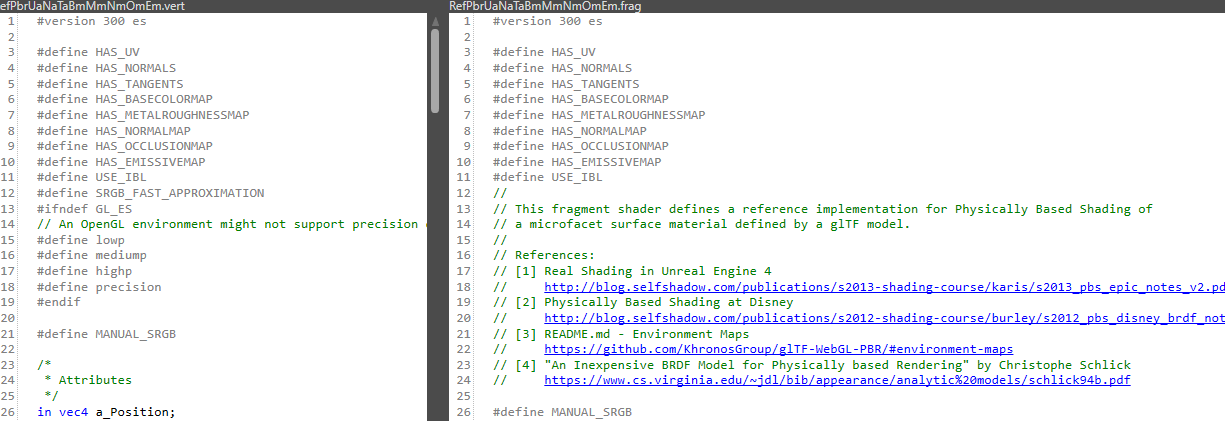
Uniform Setter:
| Optional | Uniform Setter | Description |
| model view projection | Provide the mandatory model view projection. | |
| model matrix | Provide the mandatory model matrix | |
| normal model matrix | Provide the normal model matrix, which is mandatory if the shader defines HAS_NORMALS and HAS_TANGENTS. |
Optimization Tips:
- Use one texture for occlusion, roughness, and metallic values, stored as an RGB texture.
- Providing tangents in the mesh avoids calculating the tangent space matrix on a per pixel basis.
For a more information about physically based rendering, see the Khronos website: metallic roughness.
Importing Transmissive Materials
When you import a glTF file that uses KHR_materials_transmission, Scene Composer automatically creates the multiple render pass configuration that transmission requires.
Render Targets That Scene Composer Creates Automatically
Scene Composer creates the following two render targets and links the offscreen render target to the onscreen render target.
| Render Target | Description |
|---|---|
| OnScreenRenderTarget | The render target that appears on the screen. The Copy camera and the Transmission camera render into this render target. |
| OffScreenRenderTarget | The render target that renders the area behind transmissive objects. The Opaque camera renders into this render target, and the transmission rendering references the result. |
Cameras That Scene Composer Creates Automatically
Scene Composer creates three cameras in the imported scene and assigns each of them to a render target automatically.
If the glTF file contains a camera, Scene Composer creates the three cameras based on that camera and collects them into a group named <camera name>_Group. The camera names take no suffix (Opaque), _Copy, and _Transmission, respectively. If the glTF file contains no camera, Scene Composer creates GeneratedCamera_Opaque, GeneratedCamera_Copy, and GeneratedCamera_Transmission.
| Properties | Opaque Camera | Copy Camera | Transmission Camera |
|---|---|---|---|
| Render Target | OffScreen | OnScreen | OnScreen |
| Scope Mask | 1 | 1 | 2 |
| Clear Color Buffer | Enabled | Enabled | Disabled |
| Clear Depth Buffer | Enabled | Enabled | Disabled |
| Enable Swapping | Disabled | Disabled | Enabled |
| SkyBox | Used | Used | Not Used |
| Create Mipmaps After Rendering | Enabled | Disabled | Disabled |
The Copy camera is the main camera for the on-screen display. If the glTF file contains a camera, Scene Composer sets the position and the look-at direction of the Copy camera from the transformation matrix of the glTF camera node.
Scene Composer does not set a SkyBox on the Transmission camera. It sets a SkyBox only on the Opaque camera and the Copy camera.
The result that the Opaque camera renders into the offscreen render target is referenced when the Copy camera and the Transmission camera render. If the referenced texture has no mipmaps, aliasing occurs and the Roughness of transmissive materials does not appear as intended. For this reason, Scene Composer enables Create Mipmaps After Rendering automatically for the Opaque camera. For details about the property, see Properties Overview.
Scope Mask Assignment
Scene Composer assigns a Scope Mask to each imported object automatically, depending on whether the object uses a transmissive material.
| Object | Scope Mask |
|---|---|
| Objects that do not use a transmissive material | 1 |
| Objects that use a transmissive material | 2 |
Shaders and Uniforms
During the import, Scene Composer adds the following preprocessor definitions and uniforms to the shader, depending on the extensions that the glTF file uses.
| Extensions | Preprocessor Definitions | Uniform |
|---|---|---|
| KHR_materials_transmission | MATERIAL_TRANSMISSION LINEAR_OUTPUT HAS_TRANSMISSION_MAP (if a transmission texture exists) |
u_TransmissionFactor u_TransmissionSampler u_TransmissionFramebufferSampler u_TransmissionFramebufferSize |
| KHR_materials_volume | MATERIAL_VOLUME HAS_THICKNESS_MAP (if a thickness texture exists) VOLUME_UV (if the material uses a UV set other than uv0) |
u_ThicknessFactor u_AttenuationDistance u_AttenuationColor u_ThicknessSampler |
| KHR_materials_dispersion | MATERIAL_DISPERSION | u_Dispersion |
The following describes each uniform.
| Uniform | Description |
|---|---|
| u_TransmissionFactor | The transmission factor. |
| u_TransmissionSampler | The transmission texture. |
| u_TransmissionFramebufferSampler | The texture of the offscreen render target. |
| u_TransmissionFramebufferSize | The width and height of the offscreen render target. |
| u_ThicknessFactor | The thickness of the volume. The larger the value, the stronger the absorption. |
| u_AttenuationDistance | The distance, in world units, that light travels before the volume absorbs it. The shader treats the medium as homogeneous over this attenuation distance. |
| u_AttenuationColor | The color of the light that the volume absorbs. This color determines the tint of the volume material. |
| u_ThicknessSampler | The thickness texture of the volume. |
| u_Dispersion | The strength of the dispersion. A value of 0.0 means no dispersion. The larger the value, the stronger the iridescent refraction. |
For the Transmission, Volume, and Dispersion properties that apply when you use GltfAppearance, see Properties Overview.
Useful links
Khronos references include the following resources:
- glTF Overview (https://www.khronos.org/gltf/)
- glTF 2.0 Specification (https://github.com/KhronosGroup/glTF/tree/master/specification/2.0)
- glTF 2.0 Sample Models (https://github.com/KhronosGroup/glTF-Sample-Models/tree/master/2.0)
The Khronos specification is available here:
- Specification (https://github.com/KhronosGroup/glTF)
The following viewers are available:
- BabylonJS Sandbox (https://sandbox.babylonjs.com/)
- donmccurdy glTF viewer (https://gltf-viewer.donmccurdy.com/)
- Khronos glTF Sample Viewer (https://github.khronos.org/glTF-Sample-Viewer-Release/)
Skinning
Since CGI 3.14, you can import skinning Filmbox (FBX) or GL Transmission Format (glTF) files. Scene Composer can then play the skinning animations. However, the following limitations exist:
- The maximum number of joints associated with each vertex is 4.
- If the number of joints associated with a SkinningMesh is 100 or less, Scene Composer performs skinning using a shader.
- If the number of joints associated with the SkinningMesh is between 101 and 255 (maximum), Scene Composer performs skinning processing on the CPU. In this case, the performance decreases.
- CGI Studio manages rotations using Euler angles, so reproducing the animation might not be possible.
- If a SkinningMesh and the SkinningMesh's parent Transform are not identity matrices and the SkinningMesh does not appear as expected, set the identity matrix for SkinningMesh and the SkinningMesh's parent Transform.
- If you place a SkinningMesh and Joint Nodes under a Group, CGI Studio applies the changes in the Group's Transform to the SkinningMesh twice.
In addition to the above, note the following limitations when importing skinning in FBX file format.
- CGI Studio does not support FBX format FbxSkin::eDualQuaternion and FbxSkin::eBlend.
- CGI Studio does not support FbxCluster::eAdditive in FBX format.
SkinningMesh
Note that you can create a SkinningMesh that you can use in Scene Composer by importing an FBX or glTF file that contains at least one skinned mesh. A SkinningMesh that you create by importing a file has the following properties:
When you import a glTF file with Import Dynamic Appearance enabled, Scene Composer attaches a GltfAppearance to the SkinningMesh. For the individual properties of GltfAppearance, see Properties Overview.
Skin (Common Properties)

| Line Width |
This property is only available if you enable the Import as wireframe option when importing an FBX file that contains skinning. The Line Width property specifies the line width of the mesh when Scene Composer renders it as a wireframe.
|
| Enable CPU Skinning |
This property specifies whether you enable CPU Skinning. If you enable it, you can use vertex shaders other than those provided for skin with Skinning Mesh. Note: It is recommended to avoid CPU skinning calculations because they are slow. If you enable CPU Skinning, edit or configure the shader in a way that skinning is not performed by the shader. |
Other Property items
CGI Studio sets the following properties during import, that are not editable:

| Joint Node | This property ses a joint node. |
| Enable Inverse Bind Matrix |
This property specifies whether Inverse Bind Matrix is enabled. If the property is enabled, the joint uses the Inverse Bind Matrix. If the property is disabled, the joint uses the identity matrix. |
| Inverse Bind Matrix | The Inverse Bind Matrix brings coordinates that are being skinned into the same space as the joint. |
Adding Imported Scenes
Import of FBX or glTF files that include skinning by using the standard procedure (FBX import procedure, glTF import procedure). After importing, create new scenes and animations from the scenes and animations in the imported resources.
- Select a scene contained in the imported resource and select Add Scene From Template... from the context menu.
- The Add New Scene 3D dialog appears.
- For more information on the Add Scene From Template... feature, see Add Scene From Template.
- The Add New Scene 3D dialog appears.
- Configure the necessary settings on the Add New Scene 3D dialog and click OK.
- Scene Composer adds the scene as a new scene in the Solution Explorer panel, in the Solution > Scenes folder.
- The Scene Tree panel displays the added scene.

CGI Studio adds the SkinningMesh to the imported scene (red frame in the right figure above).
If the imported scene does not contain any camera or light nodes, add them to the new scene from the Node 3D item in the Toolbox panel and configure the required settings.
Add a Render Target
Add the camera of the imported scene to the render target.
When a camera node is added
- Display the Render Targets panel.
- Scene Composer has already added a camera with the added scene name in the panel.
- Scene Composer has already added a camera with the added scene name in the panel.
- Select the checkboxes for the added cameras.
If the imported scene contains a camera
- In the Render Targets panel, right click on the Render Target and select Add Camera to Render Target... from the context menu.
- The Choose Item dialog appears.
- The Choose Item dialog appears.
- Expand the Scenes folder in the Choose Item dialog and select the cameras in the scene you added and click OK.
Add Imported Animations
To play the skinning animation in the Player, add the animation from the imported resource.
- Right-click an animation contained in the imported resource and select Add Animation From Template... from the context menu.
- The Add New Animations dialog appears.
- For more information on the Add Animation From Template... feature, see Create animation from template.
- The Add New Animations dialog appears.
- Configure the required settings in the Add New Animations dialog and click OK.
- You can see in the Solution Explorer, that Scene Composer created a new animation.
- You can see in the Solution Explorer, that Scene Composer created a new animation.
Play Skinning Animation
Use CGI Player to play back skinning animations in a composed scene.
- Click Play selected scenario... on the toolbar to launch the CGI Player.
- If your solution contains unsaved changes, Scene Composer opens the Save Solution dialog asking you to save the solution. Click OK in the dialog to save the solution.
- Scene Composer generates the asset file and opens it in CGI Player.
- In the CGI Panel, check the target scene from the scene list on the left side.

- Use the pull-down menu to select the animation, that you want the CGI Player to play.

- Click Play Animation in the toolbar to play the animation.
- CGI Player starts to play the skinning animation specified in the Panel.


- CGI Player starts to play the skinning animation specified in the Panel.