
Smart Importer UI
This page describes the Smart Importer dialog. The Smart Importer dialog consists of the following four parts.
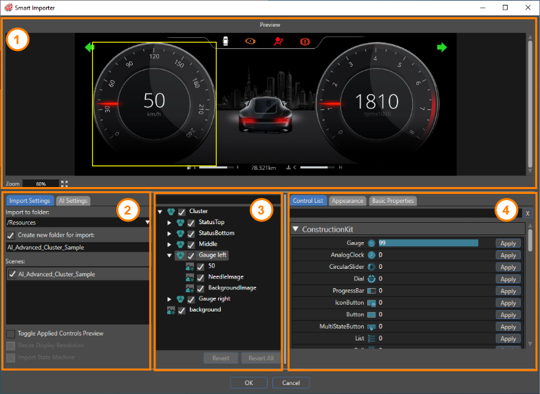
Preview
The Preview panel displays a preview of the file to be imported.
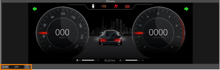
Zoom factor of the preview
The current zoom factor is displayed in the lower-left corner. To adjust the zoom factor of the preview:
- Use the mouse wheel to zoom in and out.
- Click the button with the four arrows to preview the file at the maximum zoom factor within the display area.
Select an element on the preview image. Artificial intelligence (AI) detects controls on the selected element and lists them in the Control section.
Import
The import section consists of two tabs, Import Settings and AI Settings.
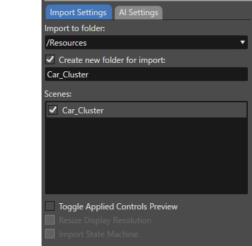
Import Settings Tab
The Import Settings tab contains the following settings.
| Import to folder |
Select a destination folder for the imported resources. To change the destination folder, use the pull-down menu. create a new destination folder, use the Create new folder for import section. The destination folder can be any location in Solution Explorer. |
| Create new folder for import |
When this option is enabled, a new import folder can be created with any name. The created folder is located in the import destination folder specified in Import to folder. |
| Scenes |
Edit scenes with the Smart Importer. See the Basic Operations guide for editing scenes with Smart Importer. |
| Toggle Applied Controls Preview |
When this option is enabled, a green frame appears where the control is applied. The green frame allows you to visually check where the control is applied on the preview. |
| Resize Display Resolution |
This option is enabled when the resolution of the file to be imported is larger than the solution's display resolution. When this option is enabled, the Smart Importer automatically resizes the resolution of the imported file to fit the display resolution. |
| Import State Machine |
When this option is enabled,the Smart Importer imports state machines from your design file directly into your CGI Studio solution. If a global state machine already exists within your solution, the Smart Importer displays a prompt where you can choose whether to import the new state machines with the Is Global property enabled. |
AI Settings Tab
Configure AI detection settings on this tab.
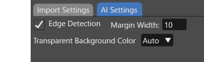
The Smart Importer uses the value specified in the Preferences for Edge Detection. For details, see the Preferences page.
AI uses the color selected under Transparent background color to analyze the image being imported. The best background color for detecting controls depends greatly on the image content.
If AI has problems detecting controls, change this setting.
Layer Tree
The Layer Tree displays a tree view of each element from the file being imported. The list displayed here corresponds to the scene tree in Scene Composer. When you select one or more elements in this list, AI detects controls on the selected elements and lists them in the Control section.
Enter keywords in the search field at the top of the Layer Tree to narrow the list to those layers that contain those keywords.
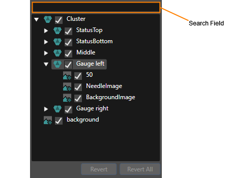
Check the checkbox to the left of each layer element to include it in the scene. The Smart Importer does not import cleared elements.
Revert/Revert All button
To cancel the applied control settings, select the target item in the Layer Tree panel and click Revert.
To cancel all applied control settings in the Layer Tree, click Revert All. The Smart Importer displays a confirmation dialog before continuing.
Control
Control List Tab
Select any layer in the Layer Tree, and AI detects the most suitable controls. The Control List tab displays the analysis results and lists candidate controls in order of probability.
The Smart Importer categorizes the controls by solution and reference, such as ConstructionKit and Custom Controls.
- For controls in ConstructionKit, the probability of matching with the AI is displayed as a number (and bar) to the right of the control name, and they are listed in descending order from the highest number.
- Custom controls that are not included in ConstructionKit are displayed in order of control name.
- By default, each category displays five controls. Clicking View All (red box in the image below) displays a list of all controls.
- The list of controls that is displayed can be narrowed down by entering keywords in the search field at the top (orange box in the image below).
- To apply the controls to the selected element, use Apply in the Control List.
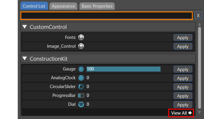
To configure the display settings, click the triangle icon on the left side of the search field. The settings section lets you configure which controls appear according to the detection value.
To apply a control to a selected element, click Apply in the Control List. When you apply a control with a low AI detection probability, a dialog box appears to confirm your selection.
Appearance Tab
When you apply any control, the display automatically switches to the Appearance tab. Configure the appearance properties for the applied control. Some controls, such as TextValue, do not require appearance settings.
The Appearance tab is made up of the following three main sections.
Image
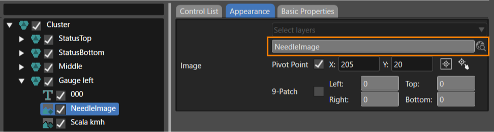
For each control image properties, select the layer image from the file to import. If the control image property name matches the layer name, the Smart Importer automatically sets the layer image. You cannot edit the image layer.
For example, when you apply the Gauge control, the Control Image has a NeedleImage property. Therefore, if NeedleImage exists in the layer name of the file to import, the Smart Importer automatically sets it to the NeedleImage property.
When you assign a control to a group layer, you can choose from the following options for the control image.
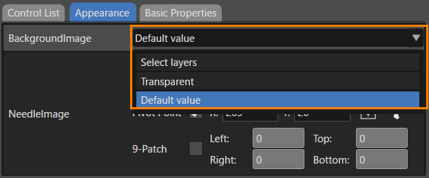
| Select layers |
Select any image layer from the group layer. You can use composite images with multiple layers. For more information, please refer to Configure a control image with multiple layers. After importing, the Smart Importer places the composite image in the ControlBitmaps folder and sets the bitmap name to the property name specified here. If you select a single layer, the Smart Importer uses the original bitmap placed in the Bitmaps folder. For folder locations, see Folder structure after import. |
| Transparent | The Smart Importer uses a transparent image. |
| Default value | The Smart Importer uses the default image for the applied control. |
Select images included in the group layer by clicking the selection icon on the right of the image.
- Select images from the descendant layers and the current layer as property values
- You cannot select layers other than images (except for bitmap layers to which controls have been applied).
- After you selected the image, the Smart Importer sets the pivot point to the center of the composite image.
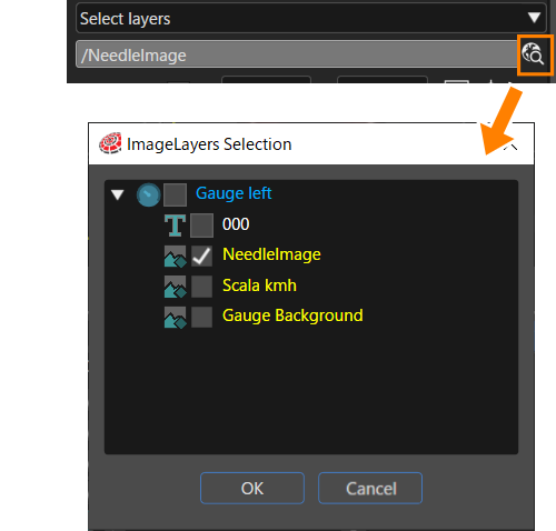
For each control image properties, set the layer image in the file to import. If the control image property name and the layer name match, the Smart Importer automatically sets the layer image.
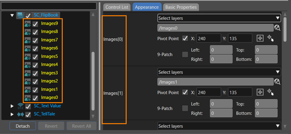
Image Array Properties
The Smart Importer supports image array properties and automatically assigns images in the FlipBook control. The numbers attached to each Image element on the Appearance tab correspond to the values displayed in descending order in the layer tree.
Folder structure after import
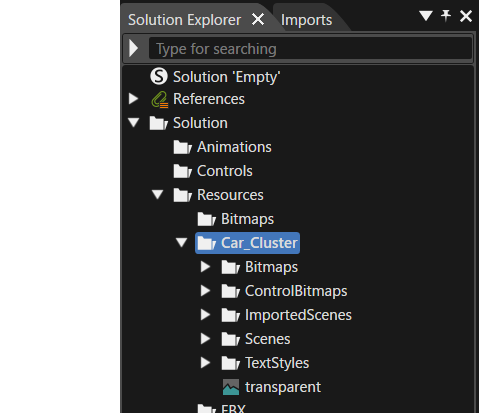
After import, the Smart Importer creates the Bitmaps, ControlBitmaps, and TextStyles folders in the Solution Explorer.
| Bitmaps | Smart Importer places the imported bitmap for each layer in this folder. |
| ControlBitmaps | Smart Importer places the bitmap composed of multiple layers in this folder for the control properties. |
| ImportedScenes | Smart Importer places the scene imported as a template in this folder. |
| Scenes | When you import a StateMachine (screen transition), the Smart Importer places the target scene in this folder. |
| TextStyles | Smart Importer places the created text style in this folder. |
Pivot Point
When you set up a control image with layer mapping, the Smart Importer automatically sets the pivot point. The pivot point values that the Smart Importer sets automatically are as follows. (However, if the pivot point values are specified with the layer names mentioned later, the specified values are used as the set values.)
- Pivot point X value: 0
- Pivot point Y value: 0
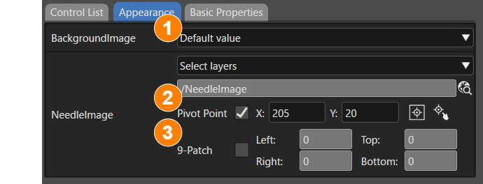
In addition, when you select the Pivot Point check box (No.1 in the image below), you can use the following options:

- Enter values for the X and Y coordinates of the pivot point. You can enter decimal values.
- Set the pivot point to the center of the image by clicking No.2 in the image above).
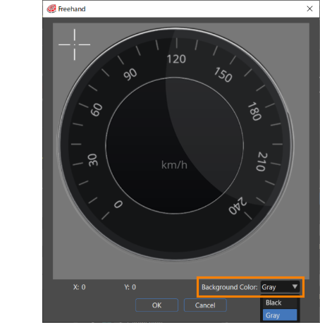
- Click No. 3 in the image above to open the Freehand dialog box. Move the crosshair cursor in the dialog box to configure the pivot point.
- Set the background color of the Freehand dialog to black or gray from Background Color in the lower-right corner of the dialog (highlighted in the orange box in the figure below). Additionally, configure the default background color in Preferences > Smart Importer.
Alternatively, you can apply any pivot point value by specifying it in the layer name of the image to import.
- If the layer name in the target file to be imported is something like
***@X10@Y20, the pivot point values are automatically set as X = 10 and Y = 20. - If the layer name in the file to be imported is
***@X10.5, the pivot point value is automatically set as X = 10.5 and Y = 0.
9-Patch
This option appears when the Enable editing 9-Patch option is enabled in the Preferences > Smart Importer settings. When enabled, the 9-Patch feature can be configured (input values must be positive numbers only).
Basic Properties Tab
This section lets you set properties for the applied control. After importing, select the target control and configure it on the Properties panel.
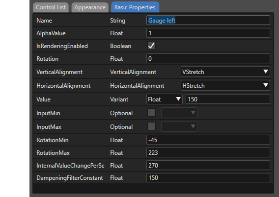
If the layer name is the same as the control's property name, the Smart Importer automatically maps the individual properties from the file to import.